Underwater Tunnel Acrylic Panels — Cast PMMA Segments, Geometry, Loads and Project Interfaces
Curved PMMA geometry, segment joints, thickness inputs, fabrication constraints and installation sequence for underwater tunnel projects.
PG Acrylic manufactures and supplies structural cast acrylic (PMMA) viewing panels for pools, aquariums and underwater structures — including the underwater tunnel panels this note covers. An underwater acrylic tunnel is not simply a series of curved panels. Panel geometry, hydrostatic loading, segment joints, fabrication limits, installation sequence and the civil support structure must be resolved as one system before fabrication begins. Approximate tunnel dimensions, water depth, project location and any available drawing are enough to start the quotation conversation; missing engineering details can be requested later.
Tunnel joints need different preparation — and it matters before the panel goes in
Jointing between tunnel panels is not the same as jointing on a pool wall or a fish tank.
Before the sealant goes in, the acrylic surface needs specific preparation — the process is different from a standard installation, and if it isn't done correctly, the joint won't perform under sustained water pressure. This is one of those steps that looks minor in a specification document and becomes a site problem if it's skipped or done out of sequence.
We walk through the joint preparation requirements before fabrication is confirmed, not after the panels arrive on site.
What changes when you go from a flat panel to a curved acrylic tunnel panel.
A flat panel is governed by a defined set of load, span, support and serviceability inputs. A tunnel adds curvature, forming limits, multiple segment joints and a sealing sequence that must be coordinated with the civil structure.
Defined panel inputs, one perimeter interface
Thickness governed by span, depth, support conditions and serviceability criteria. One perimeter interface to design. Installation is sequential and largely reversible if something is wrong.
Curvature, joints at every edge
Thickness governed by radius, pressure profile, arc span, joint arrangement and support conditions. A joint at every panel edge. Installation sequence is a design constraint fixed before fabrication — not a logistics choice.
Sequence determines sealing
In a flat panel installation, sequence is about access. In a tunnel, sequence determines whether each joint can be physically reached to be sealed. Get it wrong and panels must be removed.
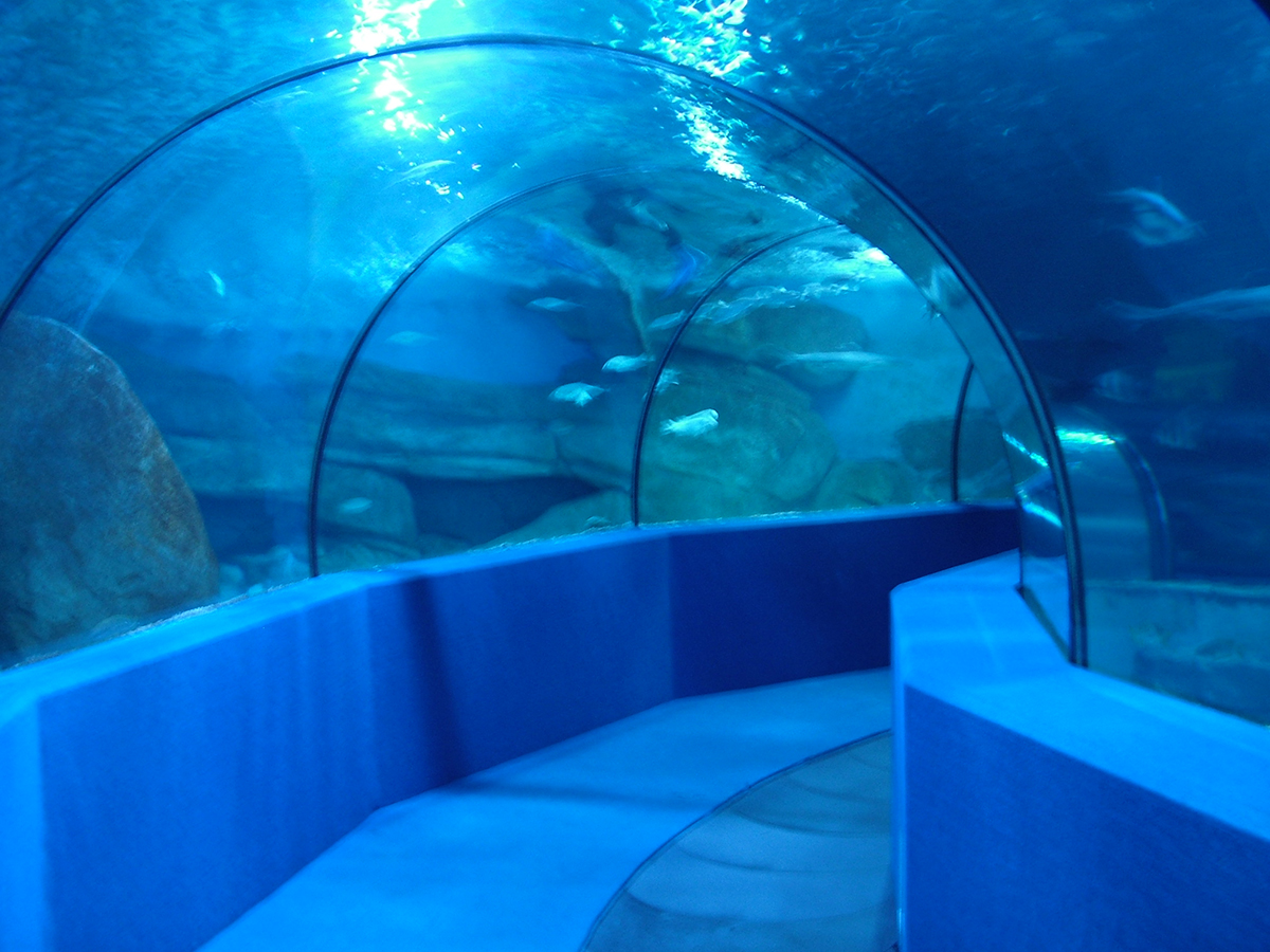
The inputs that govern tunnel panel thickness and forming geometry.
| Parameter | What it means | Why it matters |
|---|---|---|
| Internal radius | Internal radius of the tunnel cross-section | Governs curvature of each segment — smaller radius limits maximum panel arc width and increases forming complexity |
| Water depth to crown | Depth from water surface to top of the tunnel arch | Defines the pressure at the top of the tunnel arch — hydrostatic pressure increases toward the base, so the full pressure distribution across the section must be included in the structural review |
| Arc span between joints | Arc length of each segment between joint centre lines | Shorter arc spans generally reduce bending demand but increase the number of joints — and every joint is a sealing interface that has to be detailed and executed |
| Design basis | Safety factors and allowable stress criteria for the project | Project-specific — depending on the applicable design basis, load cases, material data, support conditions and approval requirements |
Cast and formed PMMA tunnel segments are engineered for the project-specific geometry and thickness. The manufacturing route is determined during the final structural and fabrication review.
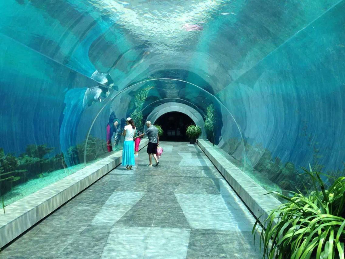
Reading tunnel dimensions and water depth correctly
Part of any tunnel review is recording what each figure actually means. Total system length, tunnel path length, developed arc length, architectural opening, visible span, single-panel dimension and panel thickness are different quantities, and drawings and reference lists often mix them. A system length must not be read as a single-panel dimension — a total formed by several bonded segments says nothing about the size of any one panel.
Water depth is the first number a tunnel review asks for, because it sets the pressure load. It is also the number most often used on its own. Depth alone does not determine panel thickness, and it does not determine geometry, support or joint design. Two tunnels at the same depth can require different panels because their radius, arc spans, segmentation and boundary conditions differ.
For that reason this page publishes no universal thickness rule. The final figure comes from the project-specific structural and fabrication review, and a thickness taken from another project is a starting question rather than an answer.
Every joint is a sealing interface that must be resolved before installation.
In a flat panel installation, there is typically one perimeter seal to design. In a tunnel, there is a joint at every segment edge — and where curved side panels meet a flat base or floor slab, on the cross-sections that use one, the transition geometry needs a dedicated joint detail.
Rebate geometry at each joint
- Rebate depth and width at each joint line
- Panel edge clearance and spring-back allowance from forming
- Rebate in the civil ring — must be cast to acrylic panel tolerance
Compression seal continuity
- Seal type and compression across the arc
- Corner seal continuity at panel transitions — crown, haunch, and base
- Access for seal replacement after flooding — not guaranteed once assembled
Base corner — a transition joint to resolve early
- Where curved side panels meet a flat base or floor slab, the geometry changes at the transition
- Usually needs a dedicated transition detail rather than a standard rebate and seal
- Difficult and expensive to correct once panels are fabricated, so the detail is resolved on paper first
Installation sequence must be fixed before fabrication
Each panel must be placed in a specific order so that the joint to the previous panel can be sealed before the next panel closes access. This sequence must be confirmed before fabrication — not worked out by the installer on site.
Sequence confirmed in the fabrication package
Installation sequence is documented and approved before panels are fabricated. Panel numbering, delivery order, and joint sealing access are all confirmed. The installer follows a defined sequence — no improvisation required on site.
Sequence resolved on site
Installer places panels in a logical order that is not the sealing order. A joint becomes inaccessible before it is sealed. The blocking panel must be removed — the sealant joint is damaged in removal, or the panel is. Rework at the installation stage is costly and can delay the project.
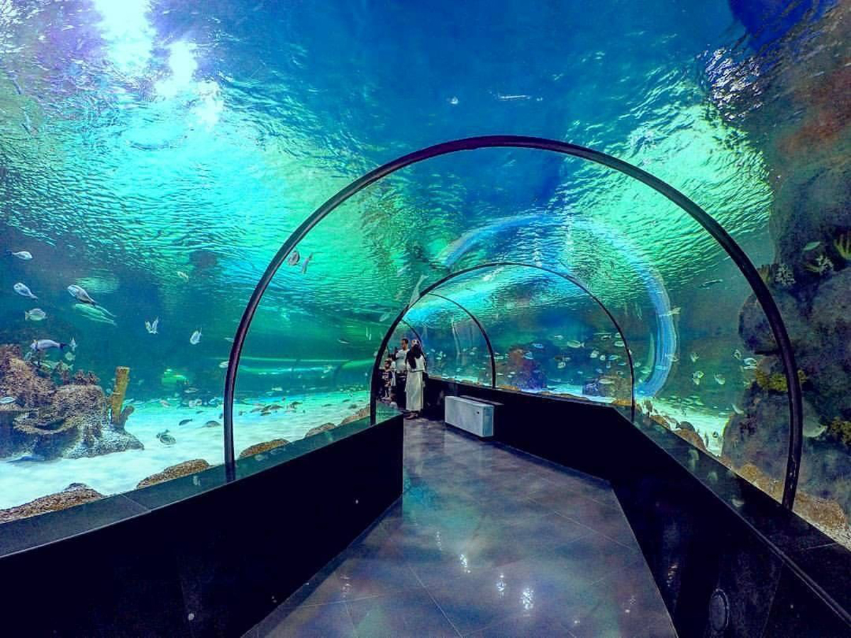
Three parties who must be in the same design conversation before fabrication begins.
Acrylic fabricator
Provides panel dimensions, forming radius tolerance, edge rebate requirements, and installation sequence. Must know structural ring geometry before machining begins — the panels are machined to fit the ring, not the ring built to fit whatever arrives.
Civil / structural engineer
Designs the bearing ring that supports the panels. Ring geometry and surface tolerance must accommodate acrylic panel edges and rebate. Ring construction precedes panel installation — errors in the ring can be difficult and costly to correct after casting.
Installation contractor
Executes the confirmed installation sequence. Must have panel delivery schedule, lifting plan, and joint sealing access confirmed before work begins. Once panels have been fabricated to a fixed sequence, changes decided on site are difficult to absorb.
Acrylic-to-civil interfaces and cumulative tolerance
The panels are fabricated to precise dimensions; the structure they land in is built by other trades to other tolerances. Those interfaces carry a large share of the coordination work on a tunnel project.
- Acrylic to concrete or steel. The recess, ring or frame the panel lands in is built by another trade, to that trade's tolerances. Which party owns the difference should be written into the scope, not discovered on site.
- Setting blocks and bedding. Panels bear on defined points or on continuous bedding — grout, neoprene or an engineered setting detail — and the bedding actually used must match what the structural review assumed.
- Waterproofing and sealant. The waterproofing line and the sealant joints around the acrylic are designed together. Where silicone is used, a structural joint and an architectural weather seal are different things and should be identified separately in the documentation.
- Cumulative tolerance. Allowances in the civil works, the frame, the bedding and the panel accumulate. Tolerances that are each acceptable on their own can stack into an interface the sealant detail was never designed to absorb, so the stack-up is checked on paper before fabrication.
Related: common acrylic panel problems — decided before fabrication →
Underwater tunnel — questions that come up on every project
How thick are acrylic underwater tunnel panels?
Tunnel panel thickness is determined project by project from the tunnel radius, water depth to crown, pressure distribution, arc span, segment and joint arrangement, support conditions, load cases and applicable design criteria. Curved geometry can improve structural efficiency compared with a flat panel, depending on restraint, segmentation, support conditions and load distribution — any thickness effect must be confirmed by project-specific structural analysis. Final thickness requires project-specific structural and fabrication review.
Why is an underwater tunnel more complex than a flat viewing panel?
A tunnel adds curvature and forming limits, multiple segment joints, sealing access constraints, civil coordination and a fixed installation sequence. Each panel must be placed so that the joint to the previous panel can be sealed before the next panel blocks access to that joint — so the sequence must be confirmed before fabrication, not worked out on site.
Why must the installation sequence be confirmed before fabrication?
Each panel must be placed in a specific order so that the joint to the previous panel can be sealed before the next panel closes access. If a joint becomes inaccessible, the blocking panel must be removed to complete sealing — removal risks damage to the sealant or the panel itself. Installation sequence is a design and constructability decision that must be fixed before fabrication because it determines whether each joint can be accessed and sealed.
How many segments does an acrylic underwater tunnel typically have?
Segment count is determined project by project from the tunnel diameter, forming limits, arc span, joint arrangement and sealing access. Not every tunnel uses the same cross-section or a flat acrylic base panel.
When is a tunnel project ready for technical evaluation?
When the tunnel cross-section, internal radius, water depth to crown, indicative joint and segment arrangement, and civil support conditions are confirmed. A cross-section drawing — even at sketch level — is the single most useful input for technical evaluation of a tunnel project.
Can a panel thickness from another tunnel project be reused?
No. Thickness follows from radius, arc span, segmentation, support conditions and water depth acting together, so two tunnels at the same depth can need different panels. A completed project shows that comparable work has been reviewed, fabricated and delivered; it does not establish a thickness for a different geometry. Another project's figure is a starting question, not an answer.
Three tunnel configurations that require different engineering decisions
Each tunnel configuration presents a different geometry challenge — and each requires a separate engineering resolution before fabrication begins.
PG Acrylic has supplied acrylic tunnel panels for completed projects in several countries. Three short references:
- Acuario Nautilus, Peru — walk-through underwater tunnel in curved cast-PMMA segments; total tunnel system length 29.96 m, panel thickness 80 mm. PG Acrylic supplied the acrylic tunnel panels. Read the project reference →
- Underwater tunnel system, Poland — total tunnel system length 20.4 m; panel thickness 100 mm. The 20.4 m figure describes the complete tunnel system, not a single-panel dimension.
- Walk-through tunnel, India — panel specifications available on request.
Read references for what they do establish: that comparable work has been reviewed, fabricated and delivered. A length or thickness from one project does not carry across to a different geometry, and a system total never describes a single panel.
The images below illustrate different completed tunnel geometries. They are not presented as the three named project references listed above.
Which configuration applies to your project? Internal radius, water depth to crown, and indicative tunnel length are the three inputs that determine which geometry constraints apply — and what needs to be resolved before fabrication can begin.
View all installed projects →Material and quality documentation for cast PMMA used in tunnel projects.
Tunnel projects involve multiple engineering parties. The following test reports and certificates are available for download to support your procurement and review process.
Related notes
Specification approach and what we need from you.
Thickness
Project-specific
Cast and formed PMMA tunnel segments are engineered for the project-specific geometry and thickness. The manufacturing route is determined during the final structural and fabrication review.
What to send us
Tunnel panels require three inputs that flat panels don't need: radius, total length, and the distance from tunnel crown to water surface. Without these, segment geometry and thickness cannot be calculated.
- Tunnel internal radius
- Total tunnel length
- Distance from tunnel crown to water surface
- Segment joint type and spacing
- Civil structure drawings if available
Need a quote for your tunnel project?
Send your approximate tunnel dimensions, water depth, project location, and any drawing you have. If more information is needed, we'll ask.